
LCD 1602 display
Some projects for the Raspberry Pi require a display to show information or messages. The LCD 1602 display is ideal for showing limited text. It is inexpensive, relatively easy to setup and program. It can show up to 2 lines of 16 characters. This project will demonstrate how to connect the Raspberry Pi GPIO pins to the 1602 LCD and then configure and display text using Python programming.
The LCD 1602 pinout is shown below.
| LCD Pin | LCD Function | Notes | Pi Pin |
|---|---|---|---|
| 01 | VSS (GND) | Breadboard GND | |
| 02 | VDD (+5v) | Breadboard +5v | |
| 03 | VO (Contrast) | Middle Pin Trimmer | |
| 04 | RS | GPIO7 | 26 |
| 05 | RW | Breadboard GND | |
| 06 | E | GPIO8 | 24 |
| 07 | D0 | ||
| 08 | D1 | ||
| 09 | D2 | ||
| 10 | D3 | ||
| 11 | D4 | GPIO25 | 22 |
| 12 | D5 | GPIO24 | 18 |
| 13 | D6 | GPIO23 | 16 |
| 14 | D7 | GPIO18 | 12 |
| 15 | A (+5V) | Breadboard +5v | |
| 16 | K (GND) | Breadboard GND |
To operate the 1602, we must send two types of data. 1) Text characters, and 2) instructions (commands) that configure and tell the 1602 what to do next. These are sent to the Data Lines – D0 through D7. Each text character and instruction requires 8 bits of data.
We will configure the 1602 to use only 4 data lines to reduce wiring connections. Within the Python program, we can send characters and instructions 4 bits at a time. First, 4 high bits are sent followed by 4 low bits to complete the 8 bit character or instruction. The 1602 pins we use are represented in the table above. Note we only use D4, D5, D6 and D7. D0 – D3 are not used.
A Read/Write (RW) pin selects the 1602’s read or write mode. We will only write data to the 1602 (not read anything from), so this pin is connected to ground – the low state which is write only. Grounding the RW pin is important to prevent potential reading of the data pins by the Pi. The 1602 uses a +5v supply while the Pi uses +3.3v on its GPIO pins. A read would cause the 1602 send data to the Pi at +5v, which could damage the Pi.
A Register Select (RS) pin tells the 1602 where in memory (register) to store the sent data. A high state (+3.3v from a Pi GPIO) stores the data in the data register (the text character). A low state (0v) stores the data in the instruction register.
An Enable (E) pin enables the writing of the data to the registers when it is ready.
The VO pin is used to control the contrast of the LCD. It is connected to a trimpot (potentiometer) to adjust the contrast.
The A pin is connected to the +5v (VDD) for the backlight.
The K pin is connected to ground (VSS) for the backlight.
6 GPIO pins from the Raspberry Pi are used to send data and commands (4 bits at a time), control the register select and enable to the LCD.
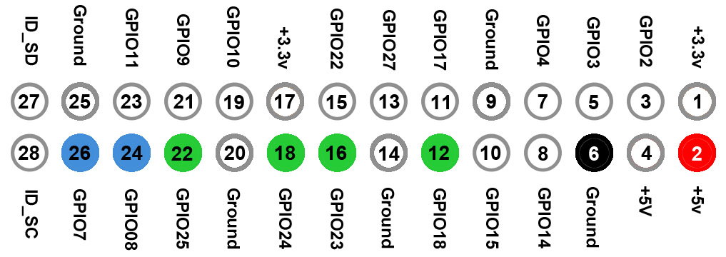
Raspberry Pi GPIO pins highlighted
The 2 blue pins are used for the RS and E signals. The 4 green pins will send data. Black is ground and red is +5v to power the LCD.

Raspberry Pi to LCD 1602 connections
The breadboard has a supply bus (row) on both sides. The horizontal row of pins next to the red line is +5v, while the blue line is next to ground. Connect your Pi to the breadboard and LCD as shown.
The trimpot spans 3 breadboard rows. One side is connected to ground with the opposite side connected to +5v. The middle pin is connected to the VO pin on the display and is used to control contrast. Once the Pi and display are operational, adjust the trimpot for best display.

Closer view of LCD 1602 pin connections
Double check your work when done to avoid damage to the Pi due to incorrect connections.
The Python Program
Following is the Python source code used for this demo. You can install the program in either of two ways.
A. Key the source code below into Raspberry Pi’s Text Editor. Save it into the Pi folder as lcd1602.py
B. If the Pi is connected to the internet, you can download it from our website as follows.
- Launch the Terminal program (command line interface)
- Type: wget -O /home/pi/lcd1602.py https://www.mbtechworks.com/files/lcd1602.py
# MBTechWorks.com 2016
# Control an LCD 1602 display from Raspberry Pi with Python programming
#!/usr/bin/python
# Pinout of the LCD:
# 1 : GND
# 2 : 5V power
# 3 : Display contrast - Connect to middle pin potentiometer
# 4 : RS (Register Select)
# 5 : R/W (Read Write) - Ground this pin (important)
# 6 : Enable or Strobe
# 7 : Data Bit 0 - data pin 0, 1, 2, 3 are not used
# 8 : Data Bit 1 -
# 9 : Data Bit 2 -
# 10: Data Bit 3 -
# 11: Data Bit 4
# 12: Data Bit 5
# 13: Data Bit 6
# 14: Data Bit 7
# 15: LCD Backlight +5V
# 16: LCD Backlight GND
import RPi.GPIO as GPIO
import time
# GPIO to LCD mapping
LCD_RS = 7 # Pi pin 26
LCD_E = 8 # Pi pin 24
LCD_D4 = 25 # Pi pin 22
LCD_D5 = 24 # Pi pin 18
LCD_D6 = 23 # Pi pin 16
LCD_D7 = 18 # Pi pin 12
# Device constants
LCD_CHR = True # Character mode
LCD_CMD = False # Command mode
LCD_CHARS = 16 # Characters per line (16 max)
LCD_LINE_1 = 0x80 # LCD memory location for 1st line
LCD_LINE_2 = 0xC0 # LCD memory location 2nd line
# Define main program code
def main():
GPIO.setwarnings(False)
GPIO.setmode(GPIO.BCM) # Use BCM GPIO numbers
GPIO.setup(LCD_E, GPIO.OUT) # Set GPIO's to output mode
GPIO.setup(LCD_RS, GPIO.OUT)
GPIO.setup(LCD_D4, GPIO.OUT)
GPIO.setup(LCD_D5, GPIO.OUT)
GPIO.setup(LCD_D6, GPIO.OUT)
GPIO.setup(LCD_D7, GPIO.OUT)
# Initialize display
lcd_init()
# Loop - send text and sleep 3 seconds between texts
# Change text to anything you wish, but must be 16 characters or less
while True:
lcd_text("Hello World!",LCD_LINE_1)
lcd_text("",LCD_LINE_2)
lcd_text("Rasbperry Pi",LCD_LINE_1)
lcd_text("16x2 LCD Display",LCD_LINE_2)
time.sleep(3) # 3 second delay
lcd_text("ABCDEFGHIJKLMNOP",LCD_LINE_1)
lcd_text("1234567890123456",LCD_LINE_2)
time.sleep(3) # 3 second delay
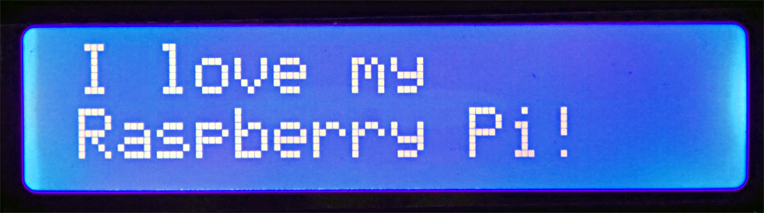
lcd_text("I love my",LCD_LINE_1)
lcd_text("Raspberry Pi!",LCD_LINE_2)
time.sleep(3)
lcd_text("MBTechWorks.com",LCD_LINE_1)
lcd_text("For more R Pi",LCD_LINE_2)
time.sleep(3)
# End of main program code
# Initialize and clear display
def lcd_init():
lcd_write(0x33,LCD_CMD) # Initialize
lcd_write(0x32,LCD_CMD) # Set to 4-bit mode
lcd_write(0x06,LCD_CMD) # Cursor move direction
lcd_write(0x0C,LCD_CMD) # Turn cursor off
lcd_write(0x28,LCD_CMD) # 2 line display
lcd_write(0x01,LCD_CMD) # Clear display
time.sleep(0.0005) # Delay to allow commands to process
def lcd_write(bits, mode):
# High bits
GPIO.output(LCD_RS, mode) # RS
GPIO.output(LCD_D4, False)
GPIO.output(LCD_D5, False)
GPIO.output(LCD_D6, False)
GPIO.output(LCD_D7, False)
if bits&0x10==0x10:
GPIO.output(LCD_D4, True)
if bits&0x20==0x20:
GPIO.output(LCD_D5, True)
if bits&0x40==0x40:
GPIO.output(LCD_D6, True)
if bits&0x80==0x80:
GPIO.output(LCD_D7, True)
# Toggle 'Enable' pin
lcd_toggle_enable()
# Low bits
GPIO.output(LCD_D4, False)
GPIO.output(LCD_D5, False)
GPIO.output(LCD_D6, False)
GPIO.output(LCD_D7, False)
if bits&0x01==0x01:
GPIO.output(LCD_D4, True)
if bits&0x02==0x02:
GPIO.output(LCD_D5, True)
if bits&0x04==0x04:
GPIO.output(LCD_D6, True)
if bits&0x08==0x08:
GPIO.output(LCD_D7, True)
# Toggle 'Enable' pin
lcd_toggle_enable()
def lcd_toggle_enable():
time.sleep(0.0005)
GPIO.output(LCD_E, True)
time.sleep(0.0005)
GPIO.output(LCD_E, False)
time.sleep(0.0005)
def lcd_text(message,line):
# Send text to display
message = message.ljust(LCD_CHARS," ")
lcd_write(line, LCD_CMD)
for i in range(LCD_CHARS):
lcd_write(ord(message[i]),LCD_CHR)
#Begin program
try:
main()
except KeyboardInterrupt:
pass
finally:
lcd_write(0x01, LCD_CMD)
lcd_text("So long!",LCD_LINE_1)
lcd_text("MBTechWorks.com",LCD_LINE_2)
GPIO.cleanup()
Show Time!
Once you have the Python program on the Raspberry Pi, launch the command Terminal and type the following command in the Terminal (in the same directory where you put the python program).
sudo python lcd1602.py
Adjust the contrast as necessary for best viewing. The LCD display should cycle through several messages until you press Ctl c.


